
Arduino Multimeter
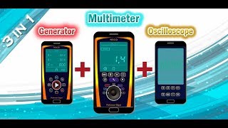
Build a multimeter on an Arduino Nano and read it on your phone. The app also turns your phone into an oscilloscope, a sound generator and a serial monitor.
Difficulty: easyMain parts: Arduino Nano, HC-05Phone: Android 6.0 or newer
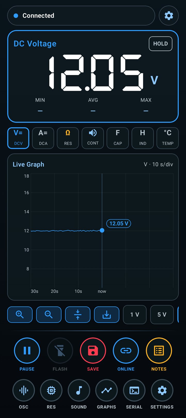
One small board, many instruments
You don't have to build everything. Each part of the circuit is independent: build only the instruments you need. The only part you always need is the Arduino with the Bluetooth module.
- DC voltage
- DC current
- Resistance, 3 ranges
- Continuity with beep
- Capacitance
- Inductance
- Temperature
- Oscilloscope
- Sound generator
- Resistor colour code
- Serial monitor
- Flashlight
Needs the Arduino boardWorks with the phone alone
Everything on one screen
Big readings, a live graph you can zoom, HOLD, and notes to save a value with a name. Save a graph to a file and open it again later in GRAPHS.
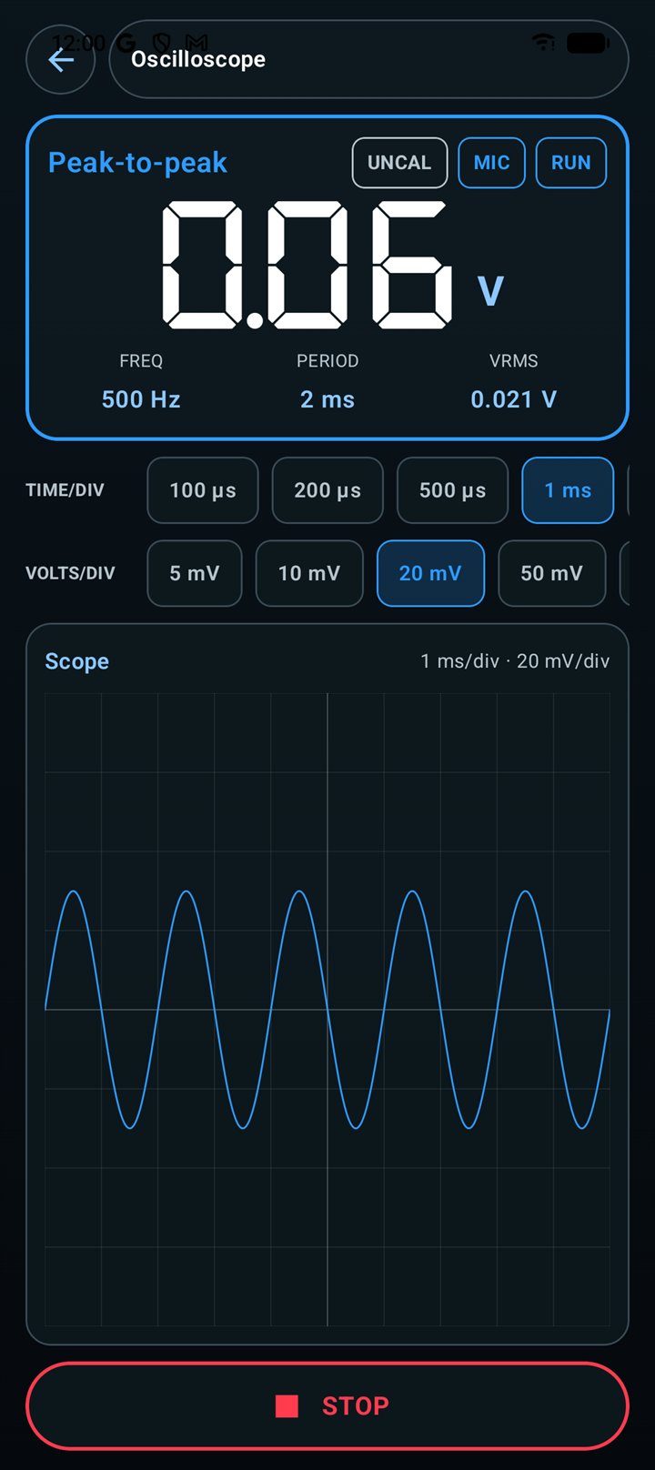
Oscilloscope
Shows the signal from the headphone input with peak-to-peak, frequency, period and RMS. Calibrate it once with a known signal.
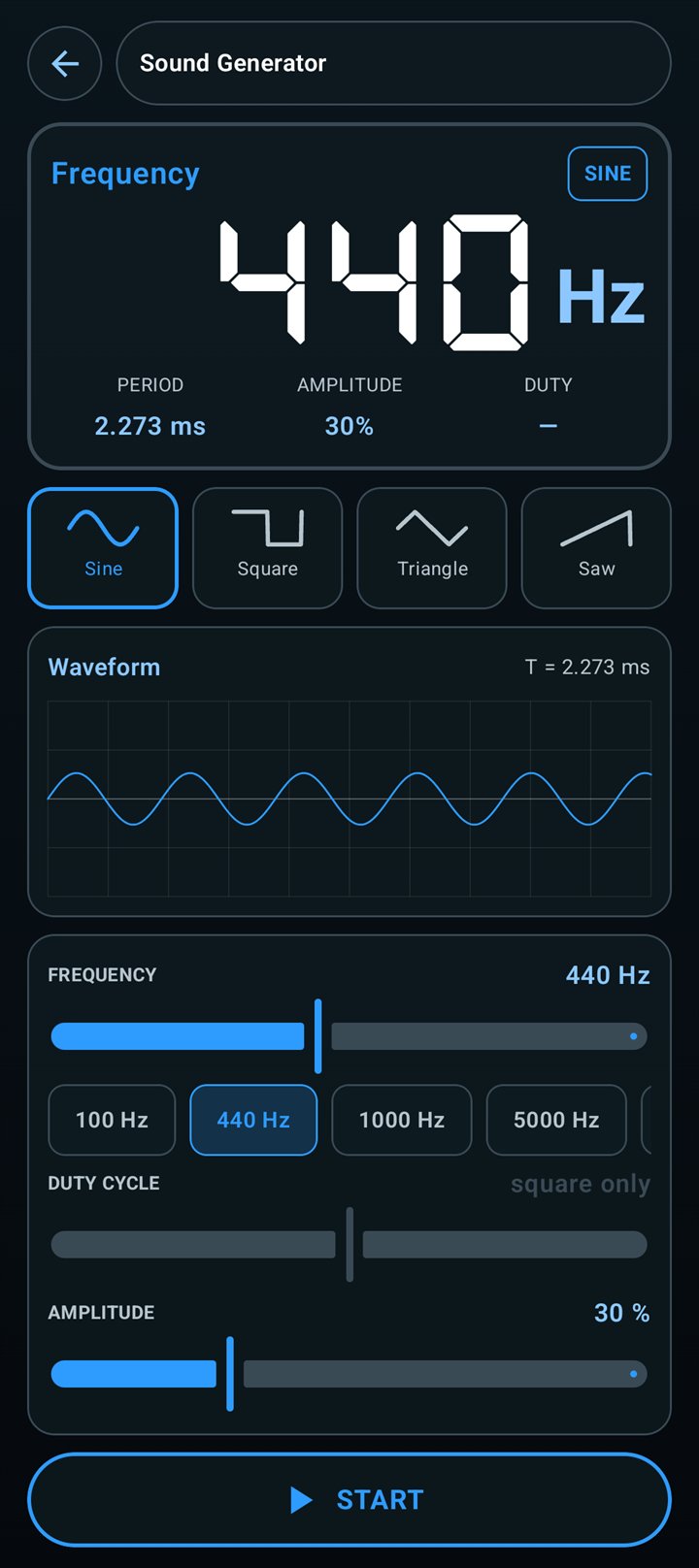
Sound generator
Sine, square, triangle and saw from 20 Hz to 20 kHz, with amplitude and duty cycle.
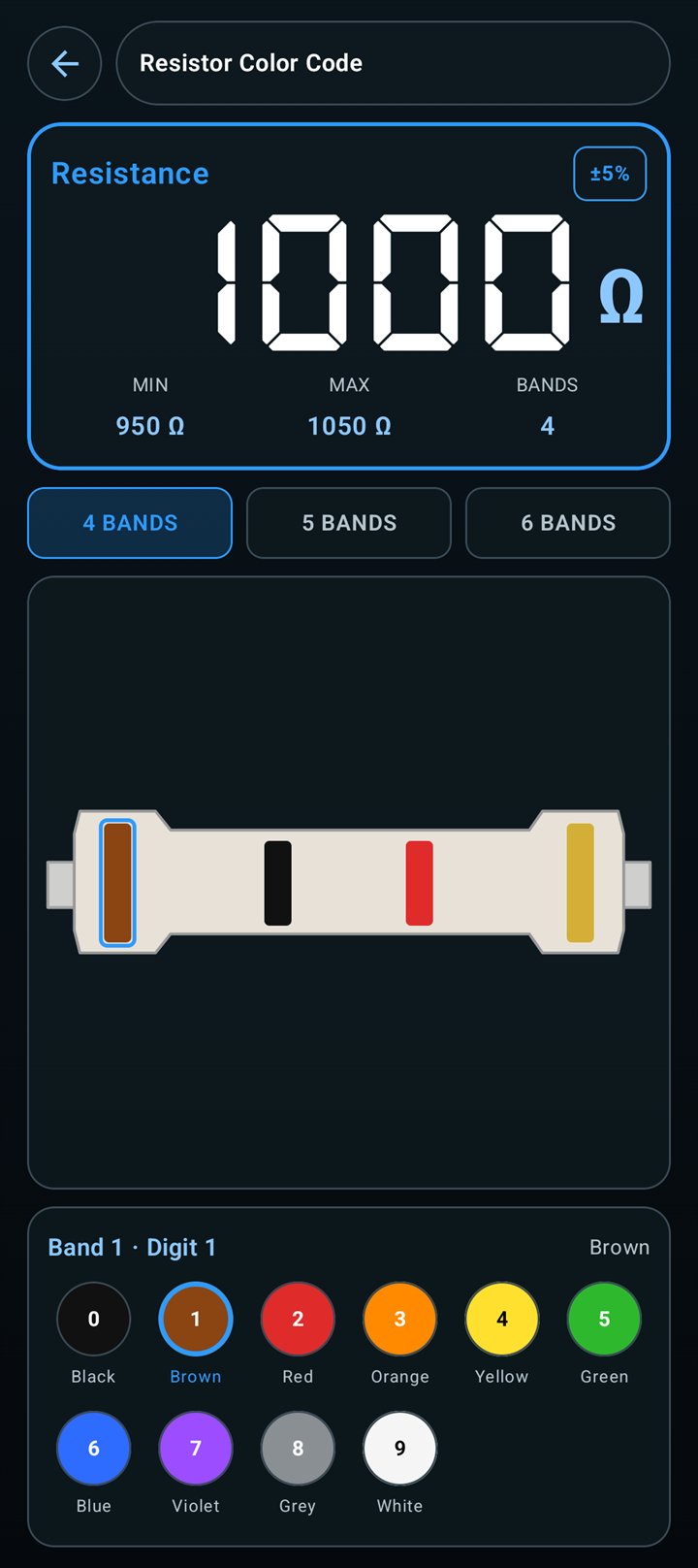
Resistor colour code
Tap the colours of a 4, 5 or 6 band resistor to read its value and tolerance.
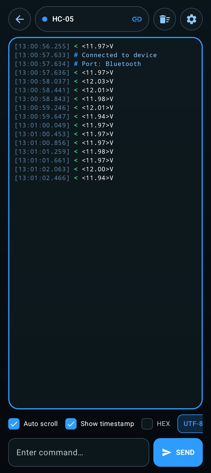
Serial monitor
Talk to any Arduino or module over Bluetooth or a USB-serial adapter: send commands, see text or HEX, set the baud rate.
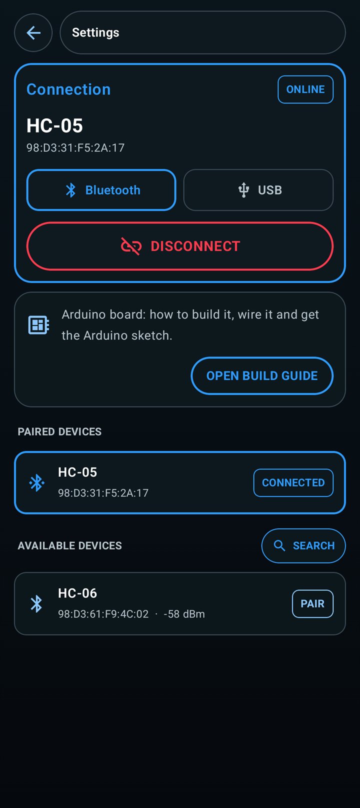
Easy connection
Search, pair and connect to the HC-05 right in the app, or switch to USB.
Live graph
Every reading goes on the graph. Pause to scroll back, zoom in, or save it with a name.
What you need
Multimeter board
- Arduino Nano or Uno1
- Bluetooth module HC-05 or HC-061
- Temperature sensor TMP361
- Resistor 10 kΩ3
- Resistor 100 kΩ3
- Resistor 220 Ω1
- Resistor 1.8 kΩ1
- Resistor 3.1 kΩ1
- Resistor 13 kΩ1
- Shunt 0.015 Ω1
- Capacitor 0.1 mF1
Inductance meter (optional)
- Comparator LM3391
- Resistor 150 Ω1
- Resistor 330 Ω1
- Capacitor 1 µF, non-polarized1
- Diode 1N41481
Also useful
A single-sided copper board to make the PCB, or a breadboard to test first. Test leads and a 3.5 mm jack cable for the oscilloscope.
Build and connect
-
1
Build the circuit
Use a breadboard to try it out, or make the printed circuit board for a tidy, reliable result. There are two schematics: the multimeter itself, and the inductance meter, which connects to the same Arduino. Tap a schematic to open it full size.
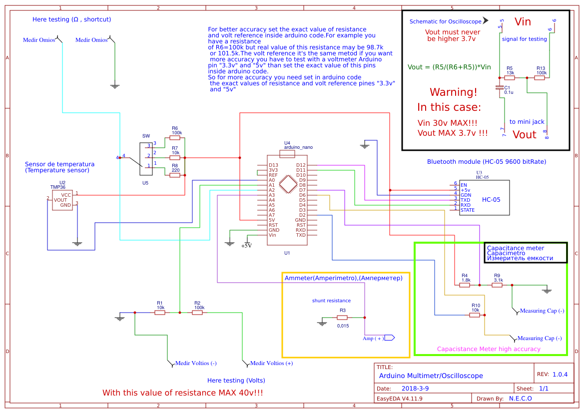 Multimeter schematic Open ↗
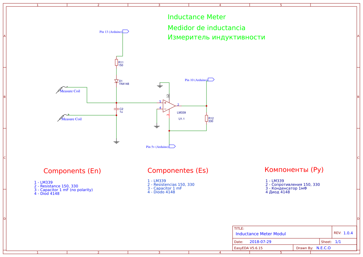 Inductance meter schematic Open ↗
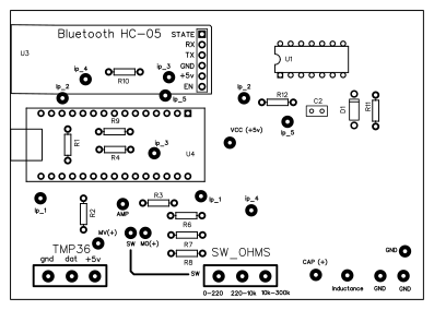 Component placement Open ↗
 PCB layout Open ↗
On the top side of the board, jumper marks show which points to join:
ip_1connects to the otherip_1, and so on. There are five jumpers,ip_1toip_5. The videos show how to make the board with the iron method and solder everything. -
2
Upload the Arduino sketch
Download the ZIP and open
multimetro_digital_premium_v1.1.0.inoin the Arduino IDE. Choose your board (Arduino Nano or Uno) and the port, then press Upload.The HC-05 connects to pins
D11(to the module's RXD) andD12(to its TXD) at 9600 baud, the module's default speed, so you can leave it connected while uploading.New in sketch v1.1.0: steadier voltage, resistance and inductance readings, and the app can tell when nothing is connected to the input. Older sketches still work with the new app. -
3
Connect the app
Power the board. In the app open SETTINGS, choose Bluetooth and press SEARCH. Tap PAIR next to HC-05 (if it asks for a PIN, try
1234or0000). When it moves to Paired devices, tap it and the app connects right away. Next time, press SYNC on the main screen to reconnect.1Pair and connect 2Readings arrive On Android 11 and older, turn on Location to search for new devices. Already paired devices work without it. -
4
Connect the test leads
Every measurement uses the common
GNDpin plus one positive pin:- Voltage
GND+MV(+) - Resistance and continuity
GND+MO(+) - Current
GND+AMP - Capacitance
GND+CAP(+) - Inductance
GND+inductance
For resistance, connect theSWpin to one of the range pins with a switch:0–220,220–10kor10k–300k. In RES and CONT the app shows BOARD SWITCH: tap the matching position, 220 Ω, 10 kΩ or 100 kΩ. WithoutSWconnected, resistance and continuity don't work. - Voltage
-
5
Calibrate for better accuracy
All the calibration values are together at the top of the sketch. With everything connected, measure with another multimeter and enter your real values:
- 5V pin voltage
SUPPLY_VOLTS - 3.3V pin voltage
AREF_VOLTS - Resistance references
R_REF_220R_REF_10KR_REF_100K - Voltage divider
DIVIDER_TOPDIVIDER_BOTTOM - Ammeter shunt
SHUNT_OHMS
Upload the sketch again after changing them. Solder all the parts: loose breadboard contacts add resistance and make readings less accurate.
- 5V pin voltage


Using the oscilloscope
The oscilloscope doesn't need the Arduino. The signal goes through a small protection circuit into the phone's headphone (microphone) input, so your phone needs a 3.5 mm jack or an adapter. To calibrate, feed a signal of known size, tap UNCAL and enter its peak-to-peak voltage.

Get everything
Schematic, PCB and sketch
Arduino sketch v1.1.0, schematics and PCB files v1.0.4 in one ZIP (14 MB).
Download ZIP