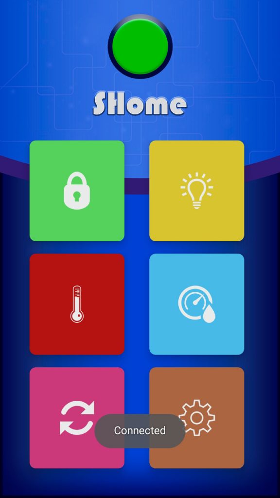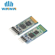
SHome is a project to control the house from an app. The app will be updated and I will add more options. It’s a project i did some time ago but it was not updated and it’s time to bring this project to life. The information of the new updates i will upload to my Blog in the SHome category, so i recommend you subscribe to my Blog to receive notification when i publish a new posts about my projects. This project is based on the Arduino microcontroller (as most of my projects). Low cost of this microcontroller, availability and easy use makes it ideal for this type of projects. Here I will explain in detail step by step how the app works and how to program the Arduino how to connect the circuit e.t.c. Smartphone goes everywhere with us, we can not even imagine life without it, that’s why it is very comfortable to use our smartphone as a remote control for Smart Home projects. As always our smartphone is with us we can control the temperature, light, humidity among other things in a comfortable way. It is the idea of this project, to control from our smartphone the electric devices without having other controls. To be able to send the commands to Arduino we will use bluetooth connection. I personally like to use bluetooth module HC-05 or HC-06 because it is easy to use it has low cost and it is easy to get. The operation is quite simple, the smartphone sends commands by bluetooth and Arduino receives the commands and according to the received command activates or deactivates the relays. The relays can turn on and off the lights of the house or other electronic devices, whatever we want. We also have a DHT22 temperature and humidity sensor connected, this sensor controls the temperature and humidity, inside the app we can establish a limit for example if it exceeds this limit the temperature activates a fan to lower the temperature or if the temperature is too low the heating is activated. The same goes for humidity, we can set a value for humidity and if it exceeds this value a dehumidifier is activated. These are basic operations of this project. Now let’s see in more detail what we will need and how to assemble all this.
Components we need:
- Smartphone with app SHome installed
- Arduino uno or arduino nano (i think you can use any arduino)
- Bluetooth module HC-05 or HC-06
- Temperature and humidity sensor DHT22
- Relay modules for arduino (in Aliexpress shop you can find very cheap relays modules)
Step 1: Pair the bluetooth module
The first thing we have to do is pair the bluetooth module that we are going to use. This we only do once and the module will be stored in the memory of our smartphone so we will not have to pair the bluetooth module every time.
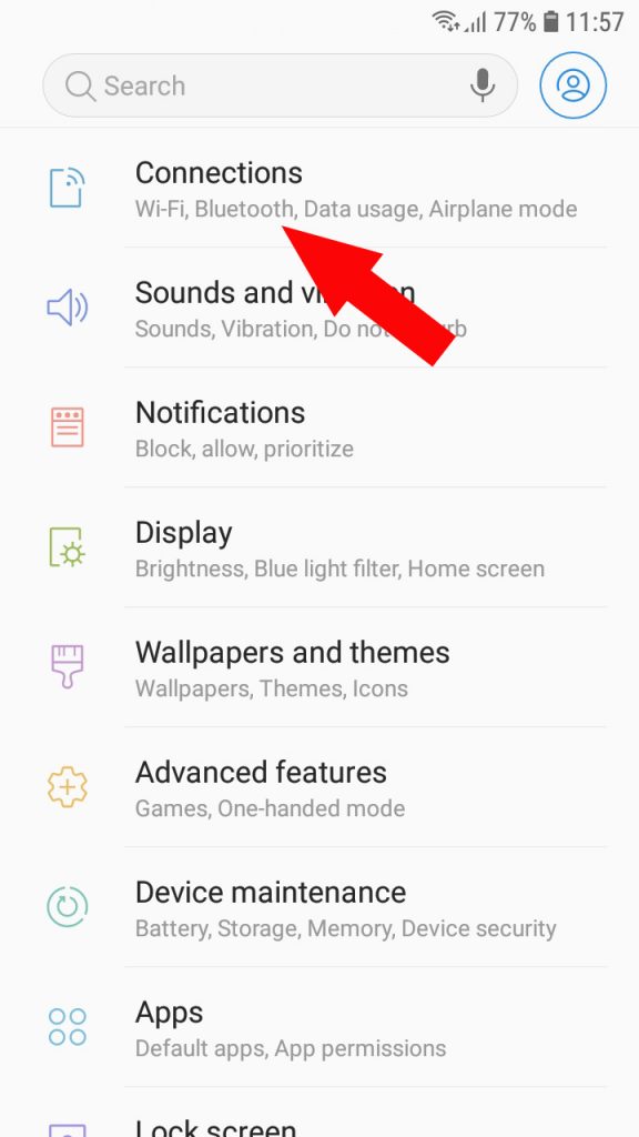
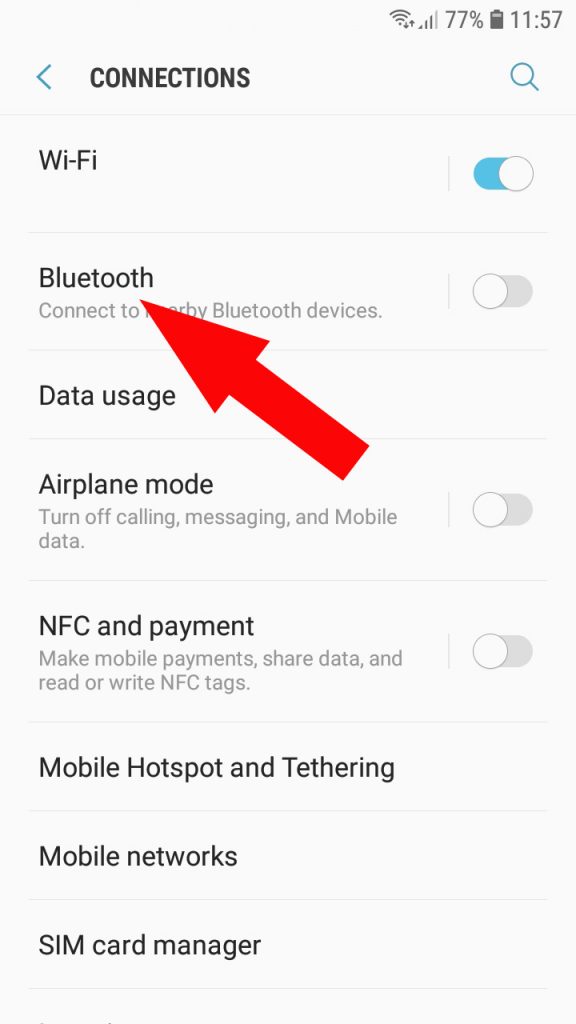
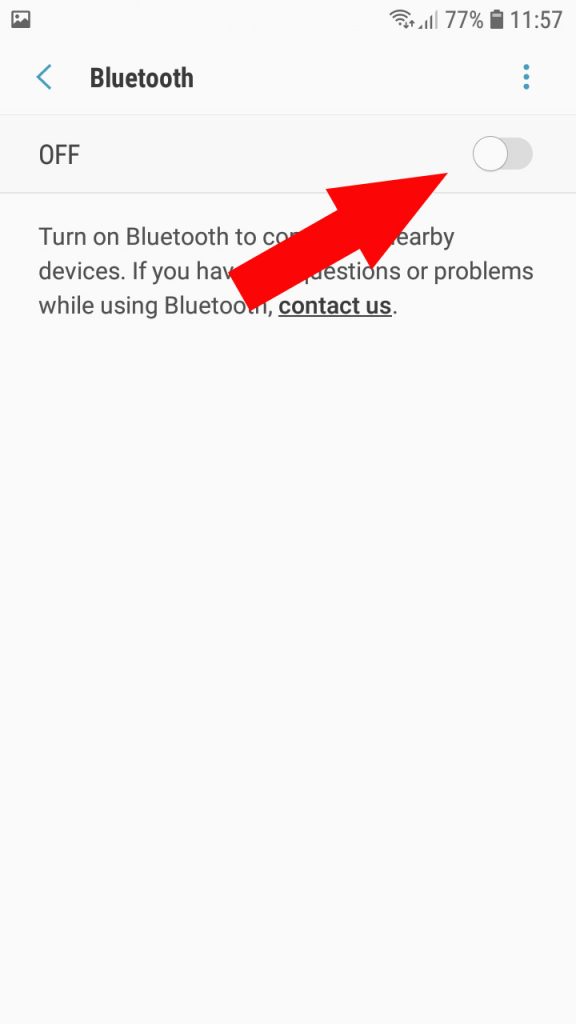
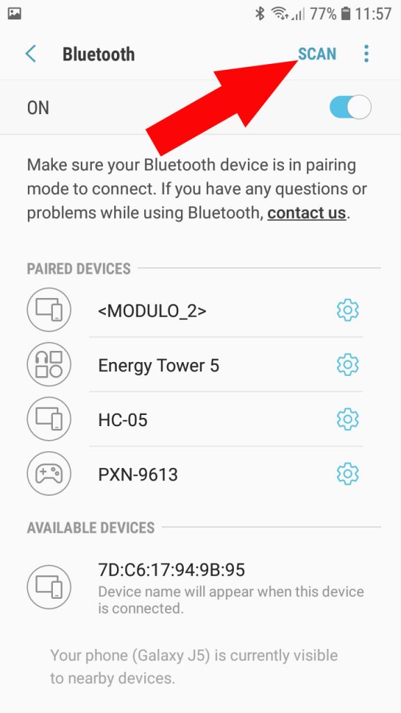
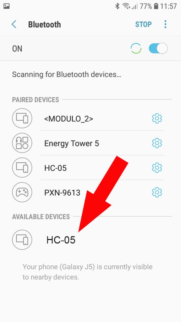
If you do not know how to pair bluetooth module keep reading if you already have it paired or you already know how to do it you can skip this step. To pair our module with smartphone we go to smartphone settings in the section Connections / Bluetooth and activate bluetooth (if it is disabled). When it is activated we press the Scan button. When smartphone finds our module we press the name of the bluetooth module and the pairing process will begin, in a few seconds it will appear that the bluetooth module is already paired. Ready, we have the bluetooth module paired with our smartphone!
Step 2: Set bluetooth module
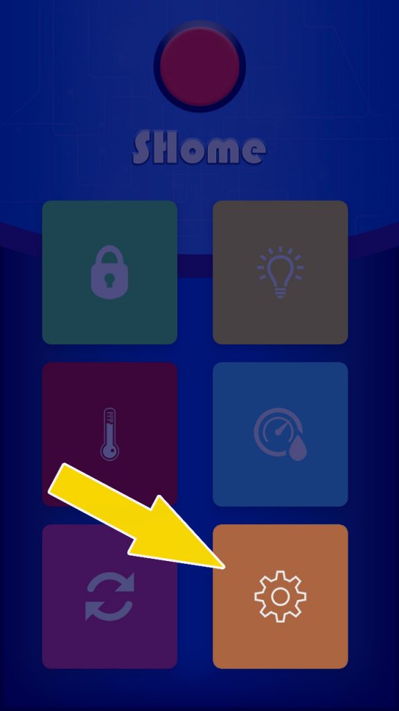
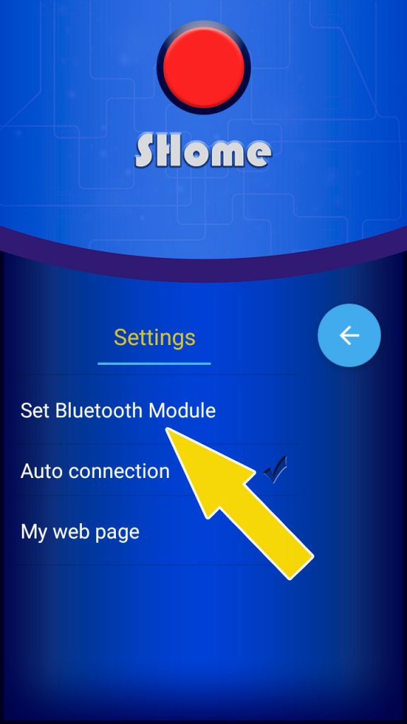
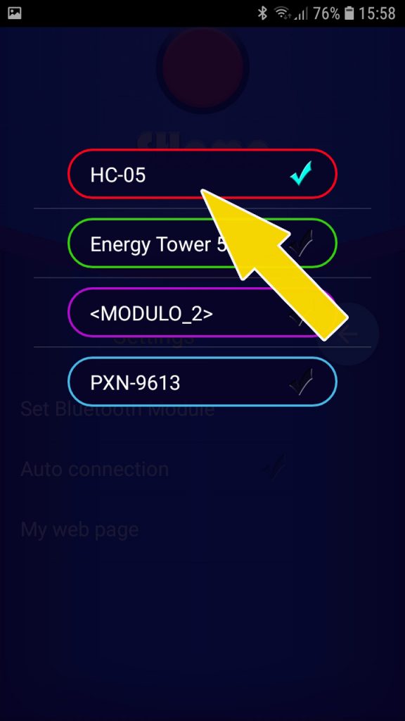
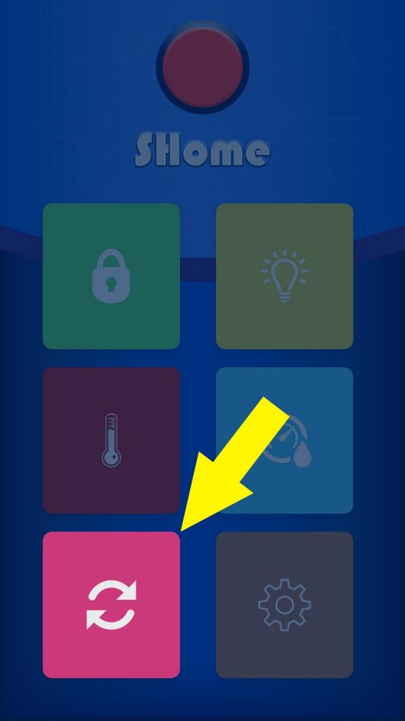
Now we have to select in the SHome app the module that we are going to use. As we have already paired the bluetooth module, it will be in the list of paired bluetooth devices. We are going to select the bluetooth module in the app. First we must activate bluetooth to be able to select bluetooth module from the list, then after on the start screen of the app we select “Settings”, we will open the Settings screen and in the list of settings we select Set bluetooth module, we will see the list of all the devices paired with our smartphone and we must choose the bluetooth module that we are going to use. Once selected it will be saved, we do not have to select again unless we want to use another bluetooth module.
Step 3: Create list of devices for control
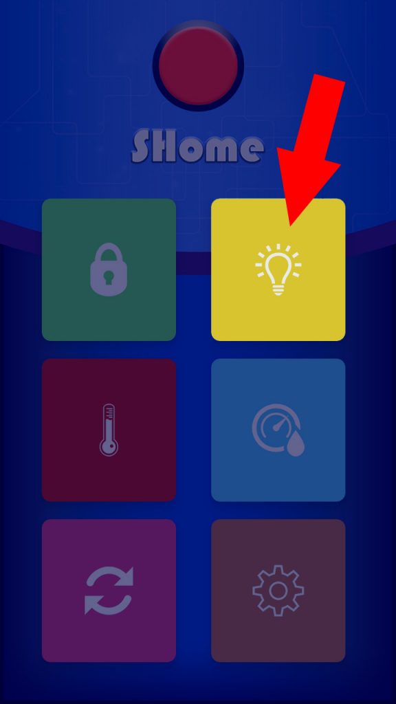
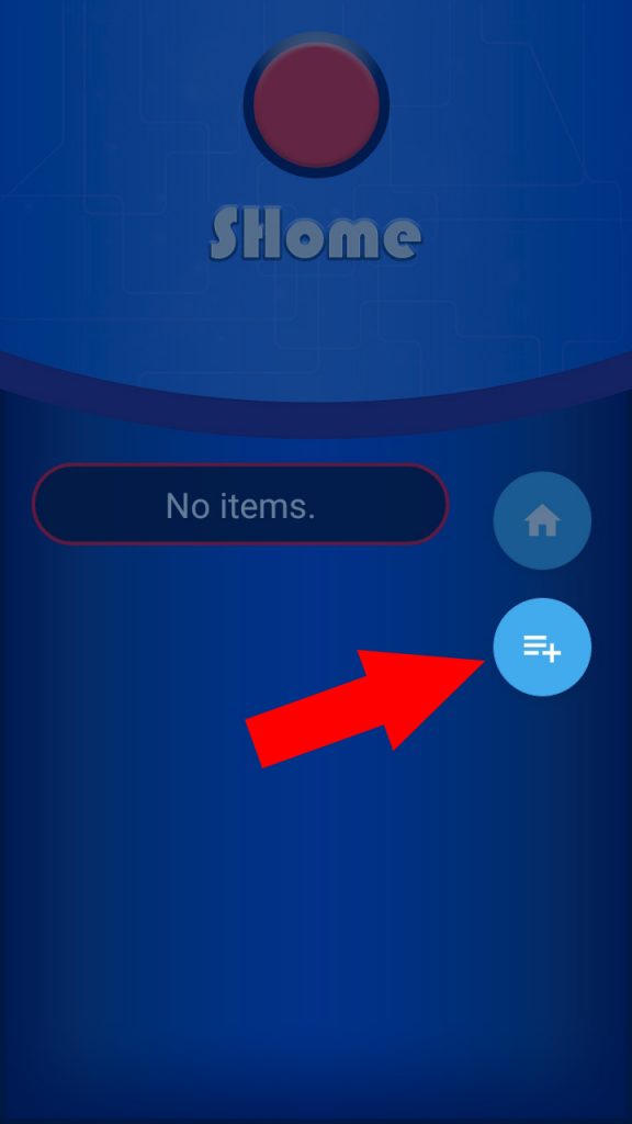
We have everything ready to start! Now we can create the list of electrical devices that we are going to turn on / off. We can turn on / off the light, fan, heating or whatever we want. In the main screen we press the yellow button and another screen will open where we can create the list of devices. On the screen that was opened, press the “new item” button (it is the button with three lines and plus symbol “+”).
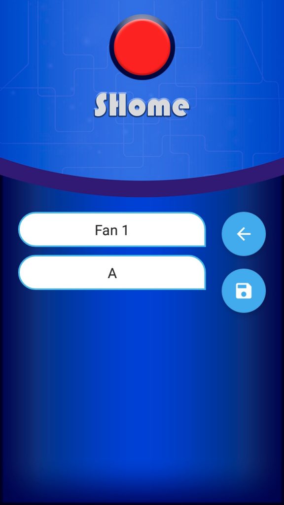
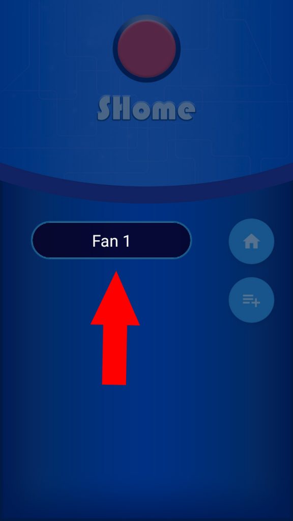
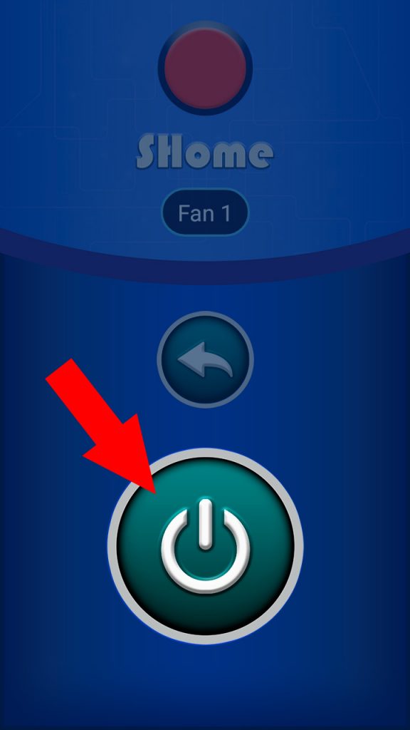
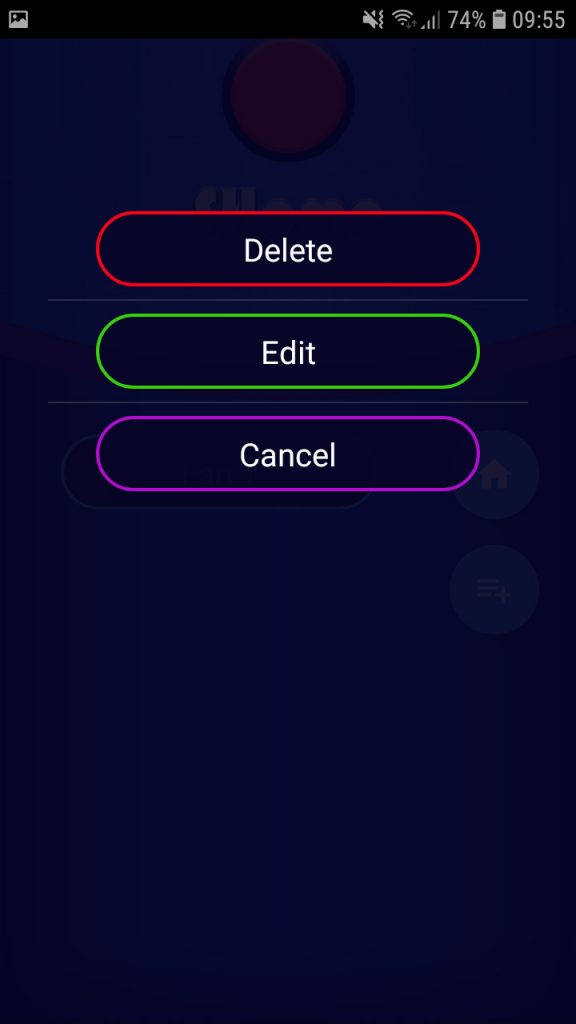
Pressing the “new item” button opens two fields to fill. The first field is the name by which we will recognize the device that we are going to turn on / off. The second field is the value that will be sent to the arduino when we press the “turn on / turn off” button, it is important don’t forget the value that we put, because we will need it for the arduino code! The value is a symbol or a letter (uppercase letter and lowercase letter are two different values and we must remember this!). Each of the new buttons created must have the unique value! This means for example if we create a button with value that is “a” lowercase we can not put the same value for other buttons that we are going to create. Below you will see the list of values in the sketch for each of the pins. A value activates or deactivates an arduino pin. So when you create the devices in the list, choose the values from the list or if you want your own values, you will have to change them in the sketch as well. An example if you created a device in the list with value “A” when you press the button to send command will activate pin 2 of the arduino and if you press the same button again pin 2 will be deactivated. IMPORTANT: do not use the numbers from 1 to 9 they are reserved for the operation of the app and should not be used. It is recommended as values to always use the letters “A” to “Z” In free version we can create 4 buttons, in Premium version as many as we will need. To modify a device in the list, click on the device in the list and the options menu will open, now you can delete or edit the device, also if we have forgotten the value we need for the arduino code, we can see it by clicking on “edit” in the menu. Now after creating the devices we have them in the list and if we click on a device in the list, two buttons appear, one is a button to return to the list of devices and the other is the button that sends the value to arduino (the value that we wrote when we created the device).
For example if we create a device “Fan 1” with value “A” by pressing the name “Fan 1” of the list appear two buttons, one large and one small when we pressing the large button will send the value “A” that we have written for “Fan 1” device. Arduino will receive the value “A” and in this way we can write the code in the arduino to do some function when it receives this value “A”. This is why every device that we are going to create must have its own letter or symbol, so that Arduino can distinguish one from the other. If you want to control more devices you can use Arduino Mega . Be cause Arduino Mega has more digital pins available
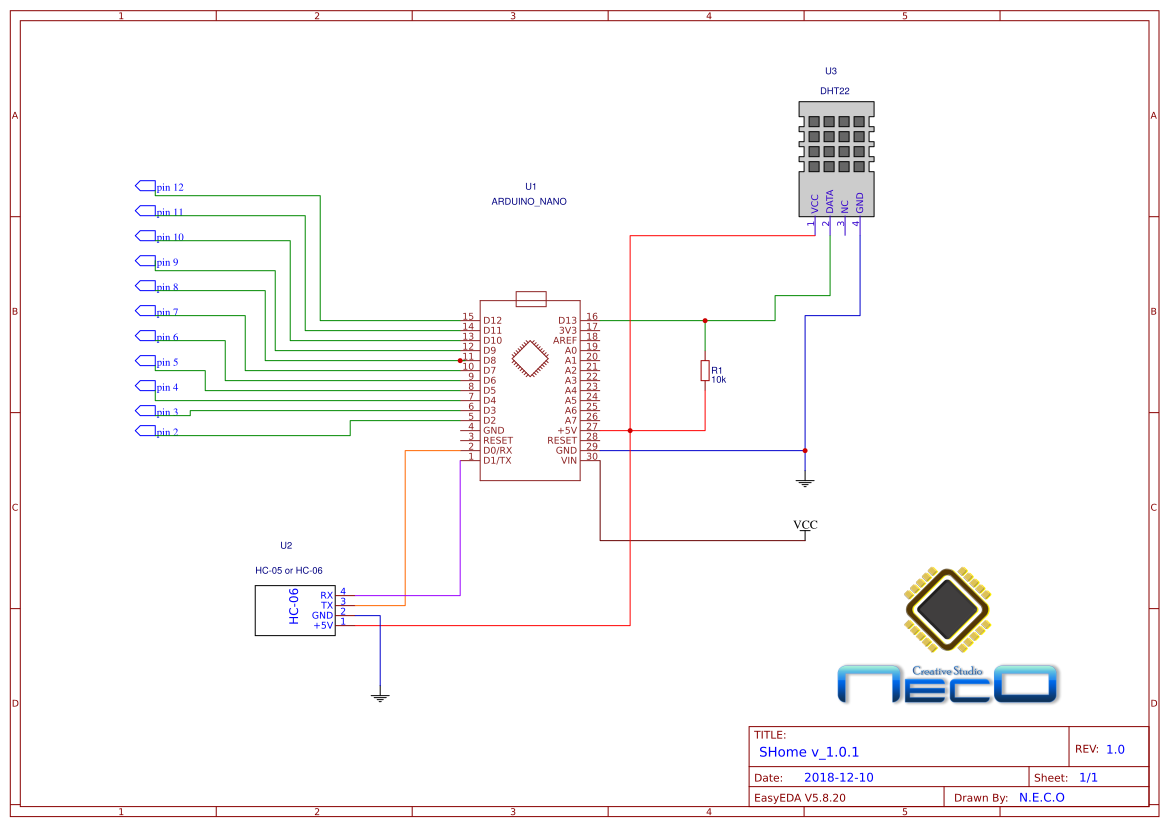
- "A"---------- turn on / off pin 2 of Arduino
- "B"---------- turn on / off pin 3 of arduino
- "C"---------- turn on / off pin 4 of arduino
- "D"---------- turn on / off pin 5 of arduino
- "E"---------- turn on / off pin 6 of arduino
- "F"---------- turn on / off pin 7 of arduino
- "G"---------- turn on / off pin 8 of arduino
- "H"---------- turn on / off pin 9 of arduino
- "I"---------- turn on / off pin 10 of arduino
- Pin 12 used for temperature control
- Pin 11 used for humidity control
- Pin 13 used for read data from DHT22
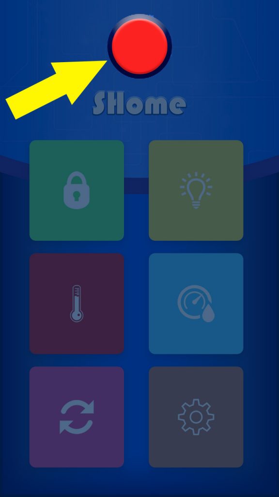
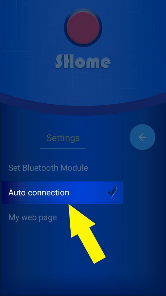
Now when we have list of created devices we can send commands to arduino, but before sending the commands we must connect to arduino, we have bluetooth module configured, so we only need to press the connect button to be able to send commands to arduino and wait a few seconds when the red icon of connection state is green, this means that we are connected to arduino and we can send the commands. If the button is red this means that we are disconnected from arduino and we can not send commands to arduino. Before pressing the “Connect” button we must not forget to turn on bluetooth on our smartphone, or if we do not want manually every time we open the app, turn on the bluetooth, on our smartphone we can activate in the menu option “Auto connection” so that when opening the bluetooth app will activate itself and when it exits it will turn itself off.
In the devices with Android version 7.0 or lower if we have activated the option “Auto connection”, when opening the app the bluetooth will be activated automatically and the app will connect to the arduino by bluetooth (if arduino and bluetooth modul turned on). In the Android version 7.0 or higher if we have activated the option “Auto connection”, when opening the app only bluetooth will be activated and to connect the app with the arduino we must press the “Connect” button .
Step 4: Temperature and humidity control
This app also allows us to control the temperature and humidity, for this we use DHT22 temperature and humidity sensor.
The sensor will be connected to the arduino and arduino will send the results of the temperature and humidity to the app. If we want to modify arduino sketch to adapt to another sensor we must know in what format the data is sent, so that the app can receive them. In order for the app to receive data from the arduino, we must encapsulate the data in the following way:
Example: for example the temperature value is 25.5 and temperature limit is 22 humidity value is 75.5 and humidity limit is 65, what we should send would be this: <25.5/22/75.5/65/1/1>. The first value must be “<“ than “temperature” than “/” than “temperature limit” than “/” than “humidity” than “/” than “2” if humidity control is turned on, or “1” if humidity control is turned off, than “/” than “2” if temperature control is turned on, or “1” if temperature control is turned off.
For example if we send the following values “<25.5 /22/ 65.5 /65/ 2/2>” this means that in the app will appear temperature 25.5Cº, 65.5% humidity, the humidity control will be activated, and the temperature control will be activated. If we send “<25.5 /25/ 65.5 /65/ 1/1>” all the same but the humidity control will be deactivated and the temperature control will be deactivated. If you do not know how to program the arduino do not worry, just download the sketch written by me, and connect everything following the schematic. I just wanted to explain the details for those who like to make their own modifications, but others can use the sketch and the schematic that you will find below. If we already have the circuit done and everything connected to the arduino, and arduino is already turned on, we can see the temperature and humidity. To see the temperature in the main screen let’s make sure the connection status indicator is green. If the indicator is green, press the temperature button and we will open a new screen.
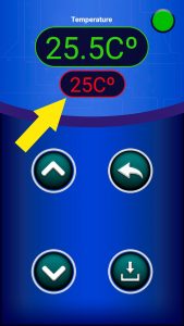
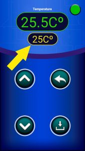
If we have done everything right we should see the current temperature. Below the temperature indicator is the temperature limit indicator in red, if it is red this means that the temperature control is disabled, if we press this temperature limit indicator, a command will be sent to the arduino to activate the temperature control and when the control will be activated in the arduino arduino send the confirmation and if everything goes well the limit indicator will turn yellow. If we want to turn off the temperature control, just press the temperature limit indicator again. We do the same with humidity control. The value in the temperature / humidity limit indicator shows when the control pin is deactivated. Example: If we have a “25Cº” value in the temperature limit indicator, this means when the temperature reaches 25ºC, the pin 12 of the arduino will be deactivated and if it drops 2ºC to 20ºC it will be activated again. If we have the temperature control indicator in red, pin 12 will be deactivated all the time. The same happens with humidity, just in the humidity the pin that will be deactivated is pin 11. I’ll explain what this means: Suppose we want to maintain the temperature at + 25Cº, we must connect to pin 12 a relay module for arduino and in the app we set the limit to 25Cº. The relay will activate a heater or something that will heat the room and when the temperature reaches the limit that we have established, pin 12 will deactivate the relay and the room will no longer heat up until the temperature does not drop by 2ºC, in this moment the heater will be activated again and so all the time to maintain the temperature in the value that we have established in the app. The same happens with humidity. To make sure that arduino has saved the value, we must look when the temperature limit stops blinking. When we start pressing the button “up” or “down” to change the temperature limit, the temperature limit starts blinking and will not stop until the app “SHome” receive the confirmation that the value is stored correctly from arduino. In this way if by pressing the “Save” button the temperature limit indicator stops blinking, we know that the value is stored correctly.
Additional Information
Press the button “Download schematic and the arduino sketch” to get the schematic and the arduino sketch. I am going to update this project, and correct the errors that may appear, if you find some error or you do not understand something write me your doubts or attachments to my e-mail: necodesarrollo@gmail.com
We download the arduino sketch and the schematic by clicking on the button, then unzip the file “zip” we will also find the folder with the library to work with the DHT22 sensor. The folder of the library is called “DHT_sensor_library_1.3.0”, this folder needs to be copied to “Documents / Arduino / libraries” without this folder, the sketch will generate an error!

