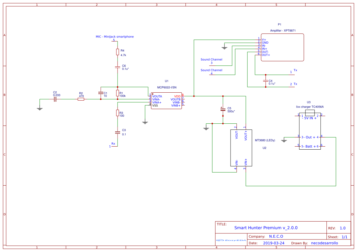
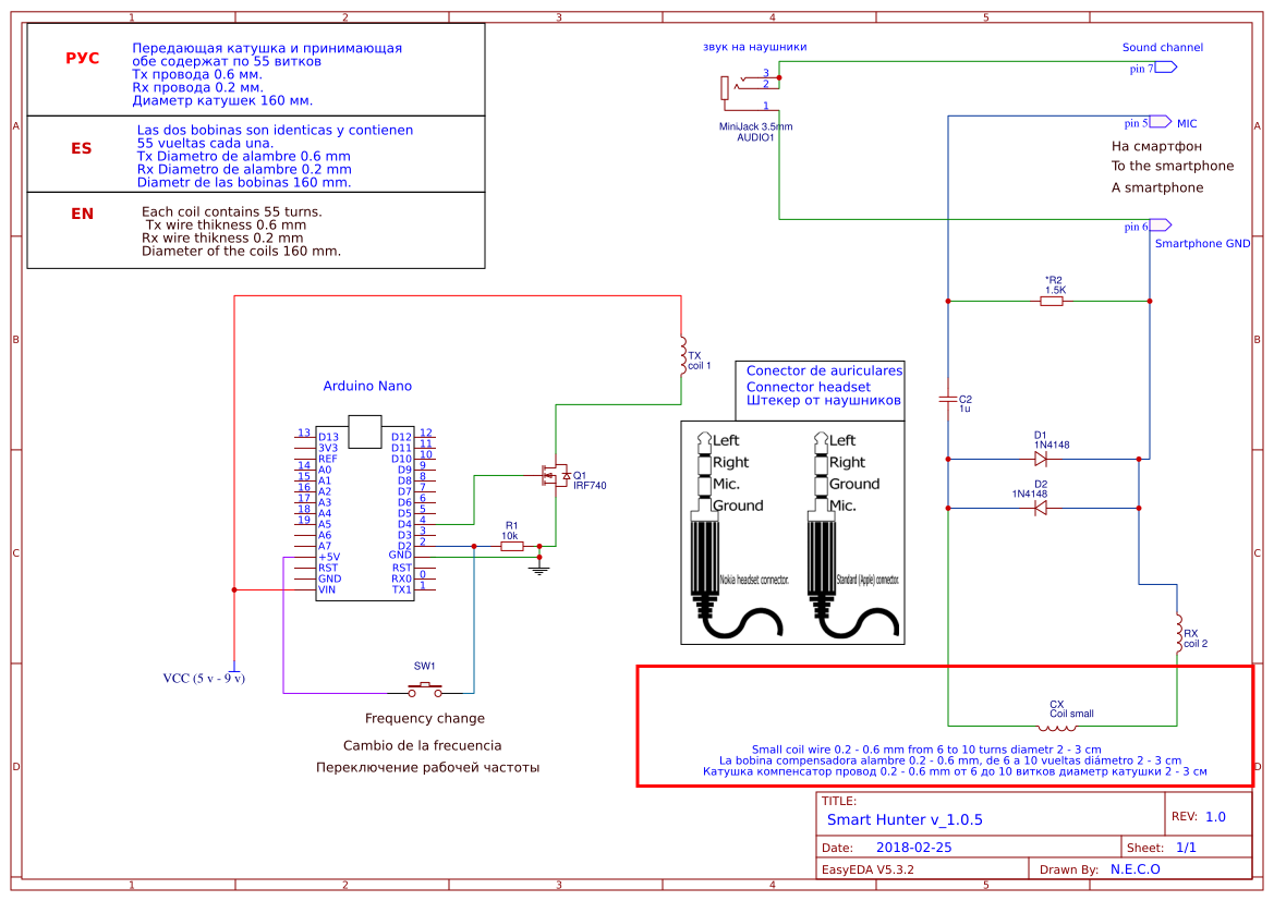
Premium version is a bit different from the free version because it has an internal generator, so in the Premium version it is not necessary to use arduino nor the MOSFET, which facilitates the assembly. The frequency of internal generator can already be chosen within the app in the PRO menu. The generator can generate from 20 Hz to 20 kHz but to detect what we are going to do we will need only from 4 kHz to 20kHz, because the working frequency of most of the “VLF” metal detectors is between 4 kHz and 20 kHz. The assembly is the same as in the free version, but in the Premium version it is easier for not using the arduino and also cheaper. Operation of the internal generator: internal generator generates the sine wave with the selected frequency and the generator signal goes to the transmitter coil (Tx), but since the signal is weak, we must amplify it, that’s why we use an amplifier. In the online store Aliexpress there are many different amplifiers, in the video tutorial i use one of those cheap amplifiers. This amplifier is cheap and very easy to use, has only input/output and power “5v” . The receiver coil still unchanged as in the free version. That means that we mount the receiver coil (Rx) as we can see in the schematic, only if we use Premium version we no longer need the arduino part. On the internet there many schematics how to make an homemade amplifier , so if somebody want to build a homemade amplifier it also will work. The amplifier used in this video has output 3 watts , if we are going to use the coil with bigger size then we must use amplifier with output 15 watts more or less ( depends on the size of the coil). Below in the section “Free Version” we can find video tutorials how to make the coils and how to adjust them, this assembly is the same for the both coils. ,


Mari
Thank you NECO2018, you’re a legend !
In your Smart Hunter version 2.0.0 you only have one Rx+ that connects to a pre-amp and one TxIn that connect to input of audio amplifier.
How do you connect the Rx- and the other TXin? Do you tie both to ground? How do you then connect the shielding around the Rx coil?
Hi
I need Premium version for Smart
hunter
هل وصلت لاي نتيجة؟
Hi,
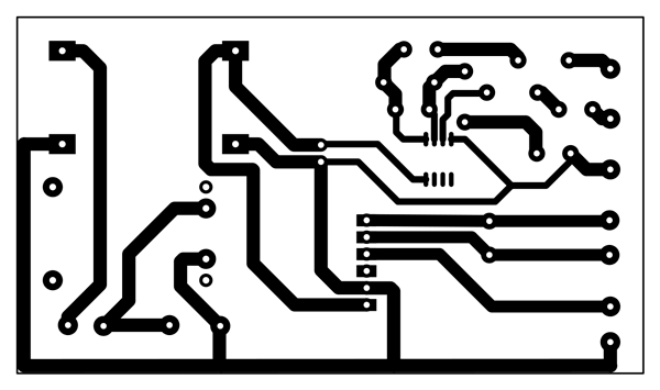
Just starting to make the Premium version circuit. In schematic there is both sound channel connected to XPT8871, but in PCB only one. Which one is correct?
In “Smart_hunter_premium_v_2.0.0\PCB Print\PCB_Smart-Hunter-Premium-PCB-2.0.0\Component list.pdf” the diagram shows component U4 but the components do not show U4. I think it should be U2.
Some of the components have a * after the units – e.g. 0.1uF*
What does the * mean?
Thanks for creating this project. I am waiting for my PCBs to arrive!
I installed the latest version of Smart Hunter but i cant see any effect in discrimination even i am premium User.
Sistem ayrım yapmıyorki yapar dememiş
I bought premium and i use external pwm signal generator 1 Hz to 150 kHz as Tx. Application is working well But i cant see any difference between discrimination or not although i set different sound.
Hi
Is version 3 compatible with the Android App currently available on the play store?
Please can you update the english V2 page?
I have just spent a lot of time, and a bit of money on buying everything for V2, only to discover in the comments that there is a V3 on the Russian page.
I am now trying to work out which components I have already ordered can be used for the new V3.
Your V3 board has no space for the charging board.
I assume that we still need the tc4056a, and we keep it off the custom PCB?
If not, how do we integrate the battery?
V2 board used mt3608 (xy-016) and V3 board uses MT3608 (LEDy).
I ordered a mt3608 but never saw the part in brackets (xy-016 / LEDy) .
Does that matter?
C11 is a 500uF capacitor. I only see 470uF capacitors commonly available.
Those 500uF that I do find are for vintage items and they seem too large for the board.
Can you give me a link to the exact 500uF that I need, or can I use 470uF?
Some of the capacitors have values but no units.
Can you confirm that I have them correct?
13 47uF C1
14 0.1uF C8
15 0.033uF C9
16 10uF C10
C7 is a 0.1uF capacitor.
C6,C5,C2 are 100nF capacitors
However, 0.1uF is 100nF
So, how is C7 different from C6, 5 and 2?
Can I use 18650 batteries for this?
What capacity would I need?
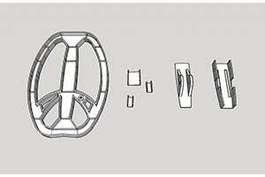
Please also add the connector from the coil bracket to the rod to your 3d models page.
Some of the components have a * after the units – e.g. 0.1uF*
What does the * mean?
Thanks for a great project – looking forward to building it!
Hi,
I am hitting the same capacitor questions, did you get an answer?
Thanks, Richard
This is very informative and exciting for those who are interested in the blogging field.
This blog is excellent to check out
Really very happy to say, your post is exciting to read. I never stop myself from saying something about
I am happy to say it’s an exciting post to read. I learn new information from your article. You are doing a great job. Keep it up
Very impressive, good job, and thanks for sharing such a good blog. Your article is so convincing that I never stop myself from saying something about it. You’re doing a great job. Keep it up
Hello
Great design, smart hunter works very well, I made the coil according to your description, but I have a question about the coil. Will the garret ace 150/250 detector’s coil be suitable? And have you thought about using some kind of operational amplifier on the RX side?
greetings
Thank yuo
I can use the loop 1×1?
Dear sir how can download software in anriod phone and how can put software Arduino nano board.thanks thaminda
I installed the app and bought the premium upgrade, but it doesn’t look anything like the interface shown in your recent videos. It has a green time series graph and numbers at the top of the screen… was this update ever pushed out to the google play store? On the top right of the app window it says V-3.0.1, while in the menu it says v-3.0.2.
I designed and built a similar metal detector, it looks like I may have the amplification too high to use with your smart hunter app even with the rx splitter at 1000… all I get are continuous targets or zero targets depending on the +/- adjustments.
What is the ‘Test value” field used for?
I want a very simple make up of the cable joints of the premium vision
Доброй ночи Сергей, не получится скачать схему для прремииум версии, файлл скачивается,но не распаковывается.
Если Вас не затруднит сниньте пожалуйста на почту. С уважением Михаил.
Your Email is not working
मुझे आपसे बात करनी है
Dear sir your software not download my phone why
Regarding Compatibility with Android App:
“Is Version 3 of the project compatible with the Android app currently available on the Play Store?”
Regarding Updates to the English V2 Page:
“Could you please consider updating the English documentation for Version 2 (V2) to clarify any differences or updates related to Version 3 (V3)? I recently invested time and resources in V2 components, but I’ve learned about V3 from comments on the Russian page.”
About TC4056A Charging Board in V3:
“In Version 3 (V3) of the project, it seems there’s no space for the TC4056A charging board. Do we still need the TC4056A, and if so, how should it be integrated since it’s not on the custom PCB?”
Regarding MT3608 Variants:
“I purchased an MT3608 for the project, but I noticed that the V3 board specifies ‘MT3608 (LEDy)’ whereas mine doesn’t have this designation (xy-016). Is this difference critical for compatibility?”
C11 Capacitor Replacement:
“C11 in the project’s components list is specified as 500uF. However, I can only find 470uF capacitors readily available. Can you provide a link to the exact 500uF capacitor needed, or can I use a 470uF capacitor instead?”
Clarifying Capacitor Values:
“For the capacitors in the project, I’ve identified the following values:
C1: 47uF
C8: 0.1uF
C9: 0.033uF
C10: 10uF
C7: 0.1uF (Is there a difference between C7 and the others?)
C6, C5, C2: 100nF (Are C7 and C6, C5, C2 essentially the same?)”
Using 18650 Batteries:
“Can I use 18650 batteries for this project, and what capacity would be recommended based on the project’s power requirements?”
Understanding the “” in Component Units:
“Some of the components in the project list have a ” symbol after the units (e.g., 0.1uF*). What does the ‘*’ signify in the component units?”
what do i need to buy exactly? from aliexpress!
0.001uf 102K 10MM
0.0022uf 222K 10MM
0.0047UF 472K 10MM
0.01uf 103K 10MM
0.022uf 223K 10MM
0.033uf 333K 10MM
0.047uf 473K 15MM
0.068uf 683K 10MM
0.1uf 104K 10MM
0.1uf 104K 15MM
0.15uf 154K 15MM
0.47uf 474K 15MM
0.47uf 474K 22MM
0.68uf 684K 15MM
0.33uf 334K 15mm
0.22uf 224K 10mm
0.22uf 224K 15mm
1uf 105K 22MM
Относительно совместимости с приложением Android:
“Совместима ли Версия 3 проекта с приложением Android, доступным в магазине Play?”
Относительно обновления страницы на английском языке для Версии 2:
“Можете ли вы рассмотреть возможность обновления англоязычной документации для Версии 2 (V2), чтобы прояснить любые различия или обновления, связанные с Версией 3 (V3)? Недавно я вложил время и ресурсы в компоненты V2, но узнал о V3 из комментариев на русской странице.”
О плате для зарядки TC4056A в V3:
“В Версии 3 (V3) проекта кажется, что нет места для платы зарядки TC4056A. Нам все равно нужен TC4056A, и если да, как его интегрировать, так как он отсутствует на пользовательской плате?”
Относительно вариантов MT3608:
“Я приобрел MT3608 для проекта, но заметил, что на плате V3 указано ‘MT3608 (LEDy)’, в то время как мой не имеет этого обозначения (xy-016). Важно ли это различие для совместимости?”
Замена конденсатора C11:
“В списке компонентов проекта конденсатор C11 указан как 500uF. Однако я могу найти только 470uF конденсаторы, которые легко доступны. Можете предоставить ссылку на точный конденсатор 500uF, который нужен, или могу ли я использовать конденсатор 470uF вместо него?”
Уточнение значений конденсаторов:
“Для конденсаторов в проекте я определил следующие значения:
C1: 47uF
C8: 0.1uF
C9: 0.033uF
C10: 10uF
C7: 0.1uF (Есть ли разница между C7 и остальными?)
C6, C5, C2: 100nF (Схожи ли C7 и C6, C5, C2 по сути?)”
Использование аккумуляторов 18650:
“Могу ли я использовать аккумуляторы 18650 для этого проекта, и какая ёмкость рекомендуется на основе энергопотребления проекта?”
Понимание “” в единицах компонентов:
“У некоторых компонентов в списке проекта есть символ ” после единиц измерения (например, 0.1uF*). Что означает ‘*’ в единицах измерения компонентов?”
Chlapi jebe mi z vás ste profíci ako sviňa ide o to,že cievku mam tesla vyrobenú na zakazku pre usa armádu nakoniec tesla zhabala Amerika ale ten detektor mam cievka je vraj nejak vinimocne natočená a na ňu chcem napojiť smart premium som laik ako rit mam iba výborných asistentov poraďte mi prosím vaetke suciastky co som videl vo videu na hunter preminum mam plosak neviem originál objednať zatiaľ no co mam robiť milujem tento koníček a nemienim sa ho zbaviť magnet fisting bol môj začiatok no som nenazrany po tom zlata som ponachadzal po starých domov jedinečné kusy starozitnosti nič nespenazujem ebem je to môj zivoy
Tak vy ste tu už od 2023 neboli to je piči
Tak vy ste tu už od 2023 neboli to je piči a mam vás v pici
Peace be upon you. I am looking for a program that works on the phone to detect metals without devices via satellite. Thank you and I am waiting for the response.