Arduino Multimeter is a project based on an Arduino microcontroller and a smartphone. It is easy to do and does not require many components. Just follow the tutorials step by step and if you have any questions contact us. This multimeter will help you in many projects and it is also very comfortable to use! Do not be scared to see that you have to mount a circuit, everything is well explained. This multimeter is wireless and uses connection with smartphone by bluetooth (HC-05 or HC-06 bluetooth module). In the future I will also add the possibility of connection by OTG cable. This multimeter can be a good tool for people who like electronic projects. The multimeter has: Voltmeter, Ammeter, Oscilloscope, Resistor color calculator, Sound generator, capacitance meter, inductance meter and much more. I often add new functions. You have the possibility to use the premium functions using the points earned in the menu, in the “Earn points” section, which consists of watching short video ads. Each video you have seen gives you points that you can then spend to use some Premium features, or you can buy the Premium version and get access to all the functions and new features that will be added in the future. Functions of this multimeter are based on an Arduino microcontroller. Arduino measures Volts, Amperes e.t.c and then by bluetooth module (HC-05 or HC-06) sends the measurement to the smartphone. The oscilloscope is connected through a protection circuit to the smartphone through the headphone input. The multimeter also has a database to store the values we measure. To save we can give a name to the value that we are going to save and brief description. Then we can see the saved values when we need them. I also recommend subscribing to my blog and my YouTube channel so I can inform you when there are new updates or new projects. When you subscribe you will receive an email with notice when I publish a new project or update. Start now and build your own Multimeter!


Hi I can not make tools .can u post me tools.thanks
Hi!What tools do you mean?Schematic and Arduino sketch?
I sand it to your mail!
Моя почта nikitin_vi74@mail.ru будет добры скинте мне схематический эскиз arduino.
Только что отправил вам на почту!Спасибо за интерес к проекту!
esta bueno necesito la versión paga (pro) pero que se le pueda consignar el dinero de forma que no sea tarjeta crédito ni debito
Can use otg cable for connection ?
Not yet. I will add OTG connection soon, but make sure your device support OTG connection!
Can it use the serial monitor?
Yes it can use serial monitore, but you need add function “Serial.println()”
En arduino sketch!
Hola Neco, podrías subir un video sobre el funcionamiento del detector de H de bobinas, estoy ensamblando el circuito, pero para decidirme comprar la versión pro de la aplicación me gustaría ver El funcionamiento del circuito, gracias!
Buenos dias!
Si claro, pero a que te refieres “detector de H”??
Hola Serjio, descargué multimetro pro para medir inductancias pero lamentablemente no muestra el valor medido, solo por instantes parpadea valores que van cambiando. También probé medir voltaje de una pila pero no muestra, solo sale 0.0v
Agradeceré me digas que está pasando.
Buenos dias!
Es un problema de conexion!
Algo conectaste mal!
Si me escribes a mi correo te ayudare a ajustar bien!
resistor wattage you have used ?
I have used 0.3w
Not able to upload the sketch to Adruino nano
Error Prompts troubleshooting#upload
Avrdude: stk recov not responding
stk getsync not in sycn
Kindly Help
You need to make sure you set the right port and you set the right microcontroller. Please open the programm and i menu “Tools”
Make sure in sevtion “Board” you set “Arduino nano”
In section “Port” port you are connect arduino.
If this not work contact ne at necodesarrollo@gmail.com
do NOT connect BT module when you do upload the sketch!
BT is connected in parallel on Rx/Tx pins used for usb/serial adapter onboard, so… you can experiment some strange behaviors!
steps:
– connect Nano to computer, alone
– upload the sketch
– disconnect Nano
– do the required connections
– put Nano in his socket
– power up
– enjoy! 🙂
PS works fine with a Mini Pro, too… 🙂
Thank you, but i don’t connect bluetooth module to Tx/Rx pin, i use bluetooth serial and i can choose pin i want to use. It only need to disconnect bluetooth module when you use Rx/Tx connection of the arduino board, but in my project it doesn’t.
Thank you!
Sergio, como va, el modulo hm 10 es posible usarlo? o solo los hc 05 y 06. Gracias por tu respuesta. Saludos
Hola Pablo! No, tiene diferente comportamiento, por eso no es posible usarlo en este proyecto, lo siento.
Hi.. Can i ask if it is possible to make the osciloscope function connected with bluetooth and not hardwired to the headphone jack. Thank you
Hi!
No, it is not posible, be cause the signal we will measure us very fast but arduino is not so fast
من اصلاهیچی نفهمیدم اگرکسی بلدیاانجام داده کمکم کنه یابرم یه دستگاه بخرم دردسرش کمتره؟
من انجام دادم واسه دوستانم حرف نداره دوست داشتی واست درست میکنم همه چیو ساپورت میکنه با باز کردن قفل سلف سنجش کامل میشه انجامدادم
تهرانم 09361006636
What are the maximum values that can be measured with this? How much current and how much voltage?
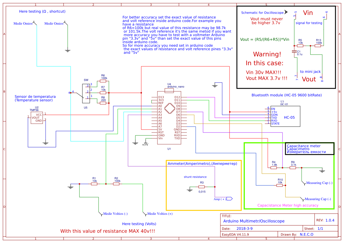
You can measure max 40 volts, but if you change resistance value you can get more than 220 volts
The current it is depend of the shunt you use.
to increase the capacity of voltage how we can use resistance is the value of resistance increse or decrese
You need open any web page to calculate the resistance values. Just write in google: ” Resistance divider calculator” and you will see lot of web page for calculate the resistance values.
How to determine the frequency
I have answered you in my YouTube channel! Thank you!
собрал схемку для осцилографа ,не работает.от встроенного динамика синусоида есть,от джека нет.пожалуйста подскажите.
Проблема в штекере, на некоторых нужно поставить сопротивление на 1.4 кОм между общим штекера и микрофонным входом. Это зависит от производителя смартфона. Иногда помогает просто выдернуть несколько раз и вставить сново штекер,
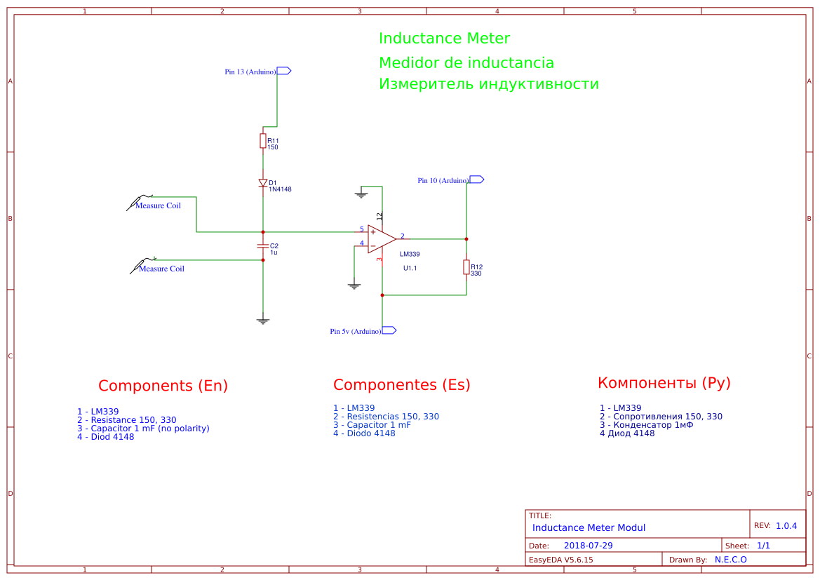
Why can’t I see on the arduino diagram that has an inductance measurement
Because i put thd inductance meter schematic on the other page, you can see it below the arduino schematic just connect them together, you can see the numbers of conbection to arduino.
what is switch interpretor?
Seitch will for chusing the rage for measuring of resistance. It is a switch wich connect one pin to 1 of 3 pines
como programar o arduino para ser usado como multimetro.
Hay que descargar Arduino sketch(lo tienes aquí, en mi pagina) luego descargar un programa que se llama Arduino IDE, esa programa ayuda a subir sketch a arduino. En el Programa seleccionamos la seccion Herramientas y donde pone Placa arduino elegimos la placa que tenemos. Luego conectamos el cable con arduino y le damos a subir, listo. En youtube tengo video tutorial
hola, disculpa podrias subir un diagrama de conexion con el arduino UNO-R3?
lo que pasa es que tengo duda en que pines conectar el modulo BT-HC-05
de antemano gracias, saludos
Los pines de arduino nano son como del arduino uno. Si en el esquematico pone D12 en arduino uno sera 12. Cada uno de los pines de arduino uno tiene su numero, y son iguales como en arduino nano, solo en arduino nano el numero va con letra “D” por ejemplo “D12” y arduino uno sin la letra “12”
Hello,
I have a question about cap selection. Not sure what to use for C1 & C2. Are both non polarity & what type (ceramic, metalized polypropylene, etc.)? Starting to source parts & looking forward to building. Thanks!
Both non polarity capacitors.I am using polipropylen. But you can use any you have
Thanks for the info, I have another question. Having a difficult time sourcing R3 – 0.015 ohm shunt/sense resistor in std .25W – .5W size. What is the max power rating that is acceptable &/or is there another resistance besides 0.015 ohm that will work? Thank you!
It is depend on voltage and Amp.
So the equation is V×A=W
Hii.. Can I use arduino mini? I bought arduino mini 16Mhz 5v and there’s no ref.
Yes, you can but measure of resistance and volts will not work
ESP32 has already bluetooth. Nice project!
Yes, and it more powerfull, soon i will do this multimeter with esp32 and i will publish it here! Thank you!
We are hurry!
Hi,
I need only ohm meter to detect resistance and recording facility with android display so which of these circuitry,sensors,and code I have to eliminate
Thx
suresh
Hi, you need only use bluetooth module part and resistance of ohmmeter module and other modules you can delete
What circuit will allow me to measure 80v or more suing
Arduino-multimeter.
Here in my web page you can finde voltage divider, you have to calculate resistance to be able measure 80v.
I wnt calculate resistance to be able measure 300v voltage divider, Vout =? 3.6v or 3.3v. Thank you!
Hi! Arduino analog pin can hendl 5 volts, so Vout = max 5 volts
Thank you. How much amperes is measured range. What if I want to expand the measuring of resistor range up to 20M? please guide.
merhaba V /I test cihazı yapabirbisiniz teşekkürler
Kardeş iyi güzel de hiç dökümantasyon bırakmamışsın!
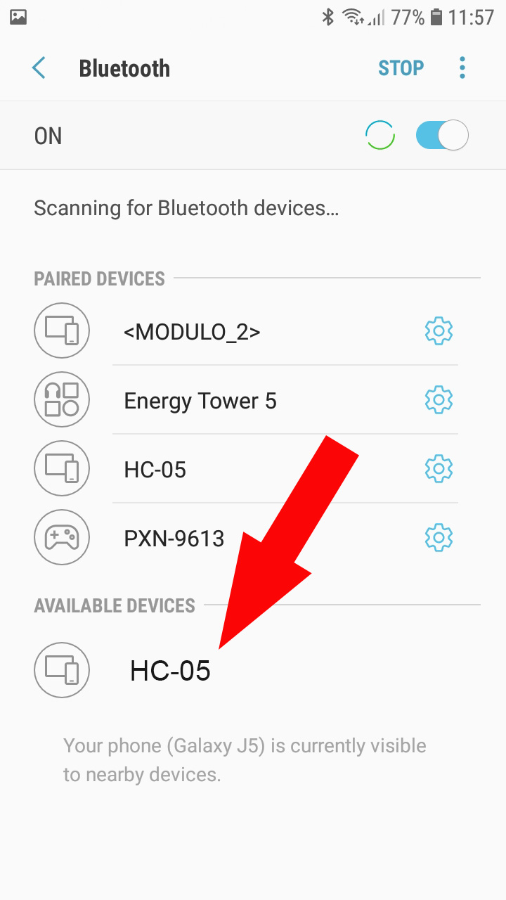
I am using the FREE version of Arduino Sketch v1.00 to test. But pairing failed – “Pairing rejected by CC41-A. V1.00 comm connection is pin 5 & 6. While the v1.03 use pin 11 & 12. I tried both and it can’t pair.
Hello, for pair bluetooth midule it must work anyway. It not important are connected pin Rx,Tx it must allow you pair divices. If you can not it can be problem of bluetooth module
Hi neco.
I been using Arduino-multimeter app for some time now and one I wish you add to your next update is the option of keeping the on (is prevent the screen from going to sleep.
Hi! Ok i will add this option!
The app keeps on disconnecting and sometimes it’s difficult to connect the app and the Arduino
Yes, this is app bug, i fill fix that in the next update
Tôi đã hoàn thành sơ đồ mạch đồng hồ và bây giờ chỉ còn kiểm định nó qua sơ bộ thì tôi thấy hoạt động tốt các thang đo riêng thang đo điện dung có vẻ hiển thị chậm nếu ở điện dung lớn
Nếu mạch ngoài được được xác định để đo điện áp 220v vậy trong ứng dụng đồng hồ có hiển thị 220v không
Hi neco can Arduino-multimeter be use to test wire continuety?
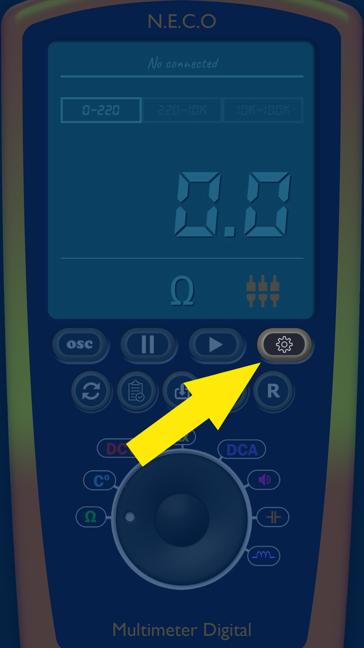
Yes it have this options. To use this option you need to set “speaker” in the app. And in arduino side resistance measuring block enough to use this function.
Hi neco can Arduino-multimeter be use to test wire continuety
Yes it have this options. To use this option you need to set “speaker” in the app. And in arduino side resistance measuring block enough to use this function
I really like this project. I’m setting up a bench to begin building a robotic project and your meter/scope would be ideal for me. Sadly, I wish I had taken a foreign language while in school. The second video you did where you mounted parts to the pcb, I don’t understand what you are saying. As a hobbyist I could use some ideas on how to mount the pcb in a box permanently. I’m also wondering if I would have any issues running this on a Samsung Tab A tablet?
No, i think it no problem to use on samsung a tablet
Hello Neco,
Would you please create scetch for esp32? It’s built in Bluetooth and more powerful. We are hurry to see it, thanks…
I have test it but esp32 have a bad ADC. This make very bad measure. For example, i have test a 1.5 volts bettery but result is 1.3 volts and for bettery 5 volts result is 6.3 volts. There is not linear accuracy. In the official web page say may be un the features they will fix it. So, esp32 to make multineter is not good idea. But i now testing STM32 and it realy goid solution. Be cause it give very good accuracy, much better arduino, and it faster. So the next update will with STM32
Thank you so much for your reply
You are welcome!
سلام
اصلا کد کامل نداره برام بفرست من میخوام آردوینو کد کپی میکنم
Bu sistemi osilaskop ve multimetre olarak kullanmak istiyorum. Hazır olarak satıyor musunuz? Çalışır vaziyette satın almak istiyorum.
Sir, best wishes to all of us, please allow me to ask for the brd pcb file. Is it possible because I have bought the premium one in the application if I can, this is my email ariyanto.boys@gmail.com thanks ….
You can download the pcb file here on my web page, it is free
parabéns amigo show
Hello Neco,
I love this project, so I assembled it myself. I used a 2-Resistor Voltage divider between D11-RXD to ensure 3.3V signal.
I checked the AO and A1 values, that these is real signal.
However, the connections between my Android Phone and BT module does not work. I assembled the temperature sensor and the voltage measuring unit. The values on the phone are changing regadless reality.
Can you please help with some tips, what to check to make ti work?
If I succeed with this curcuit, I would like to give it more popularity and publish the concept in our National Practical Electronics Magazine – if you are interested.
Thanks.
Hello ! What bluetooth module you use?
Do you know if the DSD TECH SH-H3 would work for this? Says it is the replacement for both the HC 5/6. Take the gamble for $7? Sure..
Hello! Can you help me how to assemble ohm circuit, bcs when I assembled they measured not consistent. Please!
hola,¿cuantas mediciones por segundo puede hacer arduino?, y ¿cuál es la velocidad de transferencia del módulo bluetooth?, me gustaria hacer un oscilopio bluetooth para el movil y me gustaría saber hasta que frecuencia puede medir. Gracias.
very impressive, good job, and thanks for sharing such a good blog.
Excuse me sir I want to ask about the resistor value of inductance parameter. what is the right value? 330 ohm or 330k ohm? Thank you:)
Excuse me sir I want to ask you about the resistor value of inductance parameter. What is the right value? 330 or 330k? Thank you:) because 330 in circuit image and 330k on component list
Can you please share the code
please send me gerber file i bought apk but it is hard to me to make from pdf
Dear Sir,
Could please send me the Arduino sketch file…?
Best regards,
Swad