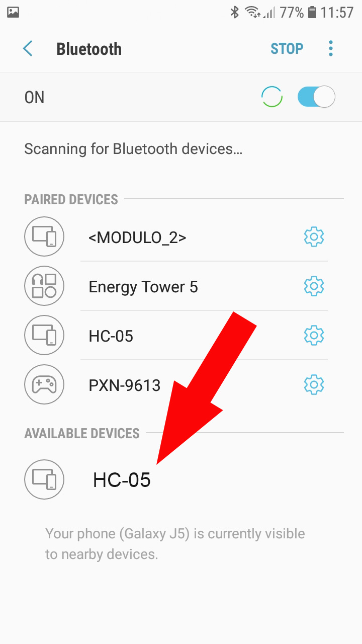
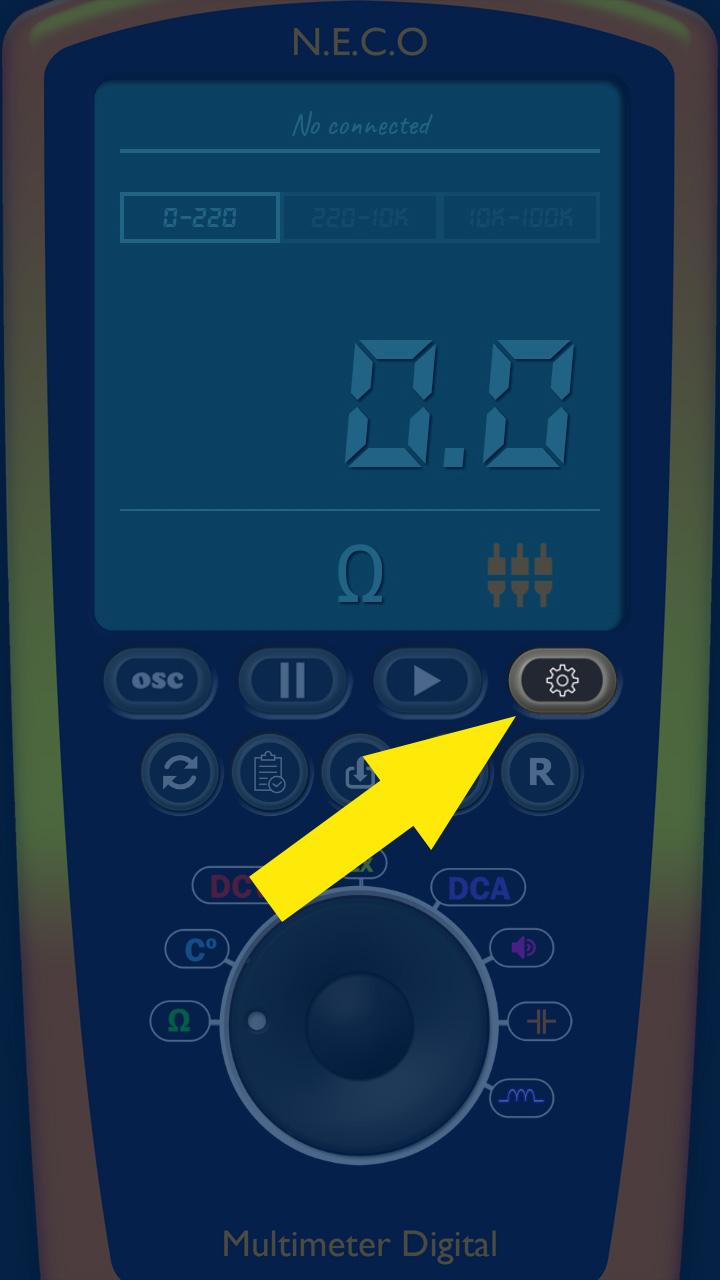
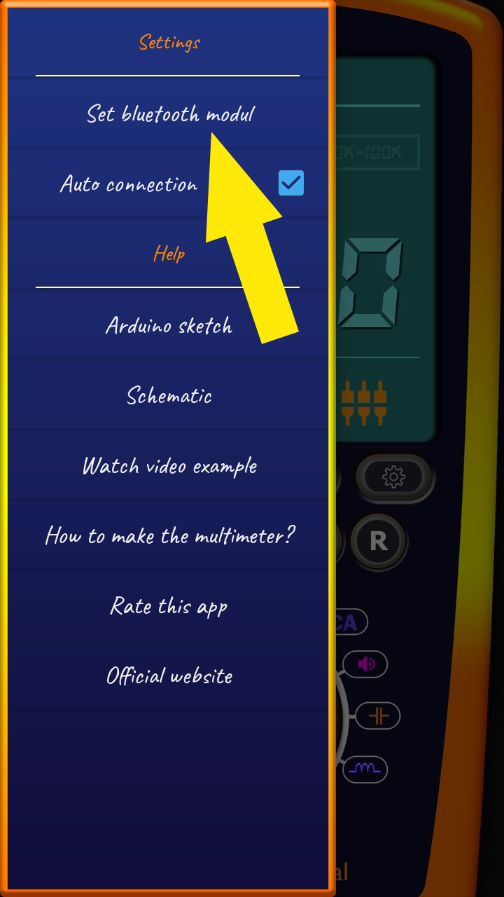
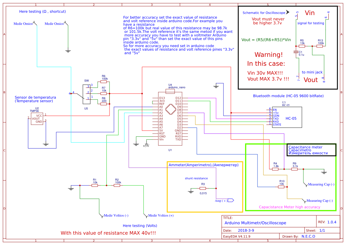
Arduino Multimeter is a project based on an Arduino microcontroller and a smartphone. It is easy to do and does not require many components. Just follow the tutorials step by step and if you have any questions contact us. This multimeter will help you in many projects and it is also very comfortable to use! Do not be scared to see that you have to mount a circuit, everything is well explained. This multimeter is wireless and uses connection with smartphone by bluetooth (HC-05 or HC-06 bluetooth module). In the future I will also add the possibility of connection by OTG cable. This multimeter can be a good tool for people who like electronic projects. The multimeter has: Voltmeter, Ammeter, Oscilloscope, Resistor color calculator, Sound generator, capacitance meter, inductance meter and much more. I often add new functions. You have the possibility to use the premium functions using the points earned in the menu, in the “Earn points” section, which consists of watching short video ads. Each video you have seen gives you points that you can then spend to use some Premium features, or you can buy the Premium version and get access to all the functions and new features that will be added in the future. Functions of this multimeter are based on an Arduino microcontroller. Arduino measures Volts, Amperes e.t.c and then by bluetooth module (HC-05 or HC-06) sends the measurement to the smartphone. The oscilloscope is connected through a protection circuit to the smartphone through the headphone input. The multimeter also has a database to store the values we measure. To save we can give a name to the value that we are going to save and brief description. Then we can see the saved values when we need them. I also recommend subscribing to my blog and my YouTube channel so I can inform you when there are new updates or new projects. When you subscribe you will receive an email with notice when I publish a new project or update. Start now and build your own Multimeter!


Hi there. My name is Hilário Scheid. I am currently working with automotive electronics, courses in this field and supplying low cost equipments and accessories to the automotive repair shops. I am giving you the sugestion of developing a multimeter software that makes the same funtions of the Fluke model 87(automotive) DMM, using the Arduino as platform. You may know more details I am talking about, please refer to the users manual of this equipment.
Best Regards.
Hilário Scheid – Electronic Engineer.
hi Hilario i like receive more information about of the post tanks
Hello, what are the ranges that I can measure with this equipment ?
Looks interesting and wanting ! BUT the documentation is difficult to follow (lousy).
Why not integrate a small help in the App ? Why not show there the link to the external module? Arduino ist nice if accustomed to it – find a simpler way without annother processor ! Perhaps just an Analogue to Digital Converter connected to the USB port. This makes the software development morde difficult but the hardware simpler, more straight forward – hopefully.
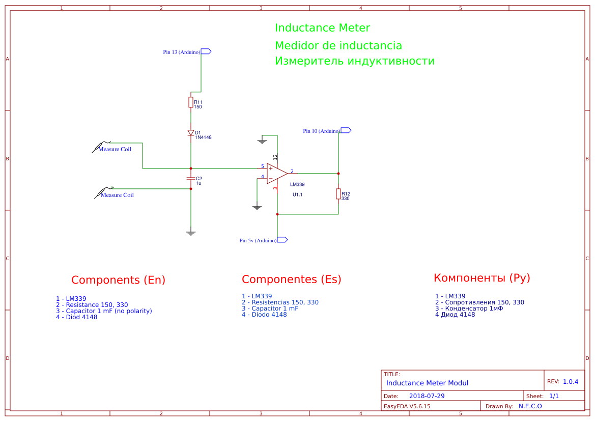
Can l please have the block diagram
Your post offers a unique perspective that challenges the conventional wisdom on the topic. It’s thought-provoking. For more details, click here.
Your post highlights the potential of creating and monetizing content in the digital age. It’s a powerful way to share knowledge and generate income. For more insights, click here.
Are you a skilled transcriptionist? click here and explore opportunities to provide transcription services for podcasts, interviews, or academic research.
Your post offers practical advice for leveraging affiliate marketing and promoting products or services that align with your audience’s interests and needs. It’s a way to earn commissions by recommending valuable solutions. For additional information, click here.
I appreciate the emphasis on leveraging one’s skills and expertise to create income-generating opportunities. It’s a reminder that everyone has something valuable to offer. To explore further, click here.
Your post discusses the potential of leveraging the gig economy and freelance opportunities as viable ways to make money. It’s a flexible and accessible option for many. To learn more, click here.
Your post highlights the potential of becoming a freelance proofreader or editor for authors, publishers, or businesses looking to ensure the accuracy and professionalism of their written content. For more information, click here.
Your writing style is engaging and relatable, making it easy for readers to connect with the money-making strategies you’ve shared. To delve deeper, click here.
So nice work you did, I appreciate this. You kept things so simple to achieve the max. I am hobbits like you. Good going, keep it up. Thanks