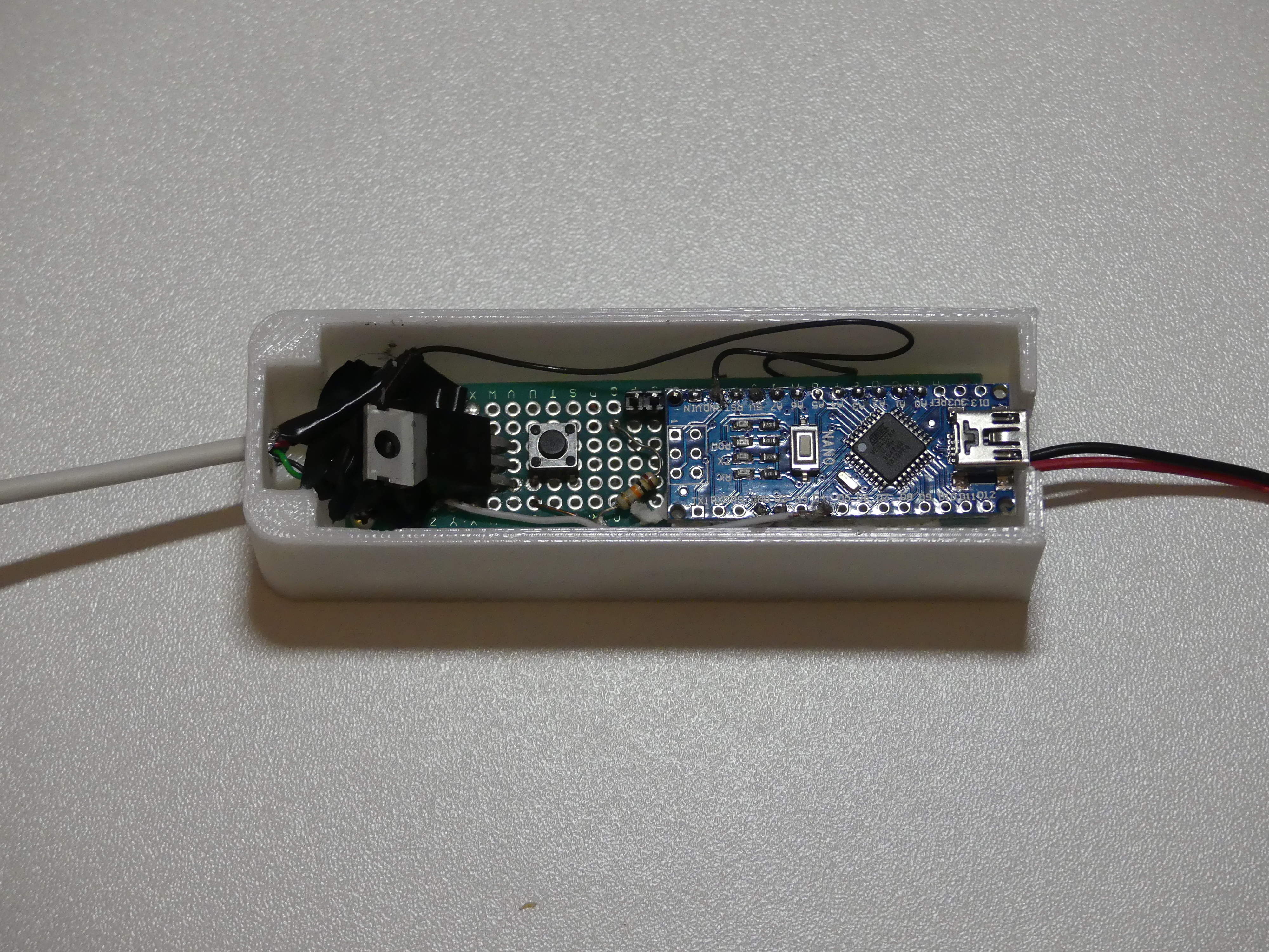
Metal detector Smart Hunter has three main parts: 1 – The coil, 2 – The app “Smart Hunter”, 3 – generator (based on arduino, internal generator or NE555 generator).The most important and hardest part to do is the coil. You have to do the coil with patience to get good results. Here I will explain what steps have to be followed to do everything right and that the final result does not disappoint us. This project is in development mode, you can try, expirement with different coils, try different generators. If you don’t understand something you can ask me here or in my email necodesarrollo@gmail.com


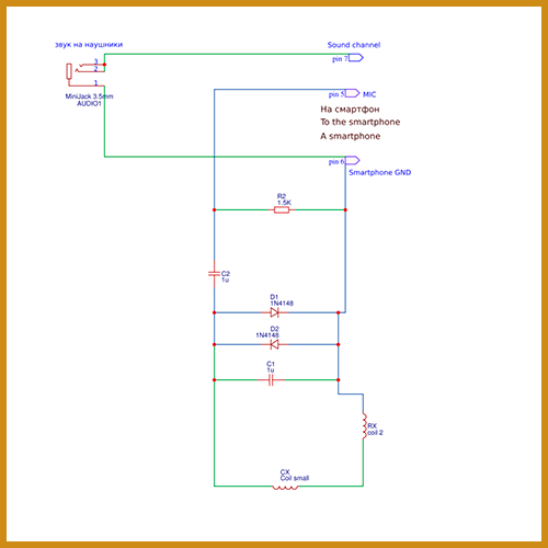


Ciao scusa vorrei sapere se ho capito lo schema cin arduino, il polo + e il polo – vanno sotto batteria supplementare, poi i collegamenti dello schema della bobina rx sul lato destro vanno collegati al connettore maschio e sul laro sinistro che quello che non capisco dove vanno collegati che sarebbero pin 6, e pin 7 grazie..
Hello, how can I discriminate metals and how I can have more sensitivity. I can have the source code of smart Hunter.
Thanks
I am not finish yet the discrimination part, to get more sensetivity you can adjust better the balance and use coil with bigger diameter
the best homemade metal detector, next to a professional … easy to build and with an excellent search .. I recommend for red earth to make shielding on coils tx / rx.
Congratis neco
Thank you Adriano!
SHOW
hola buen día, tengo problemas para conseguir el MCP6022 acá en México mi pregunta es, lo puedo sustituir por un TL082CP GRACIAS
saya masih belum tahu Ukuran membuat coil tx maupun rx, diameter, jumlah putaran , dll
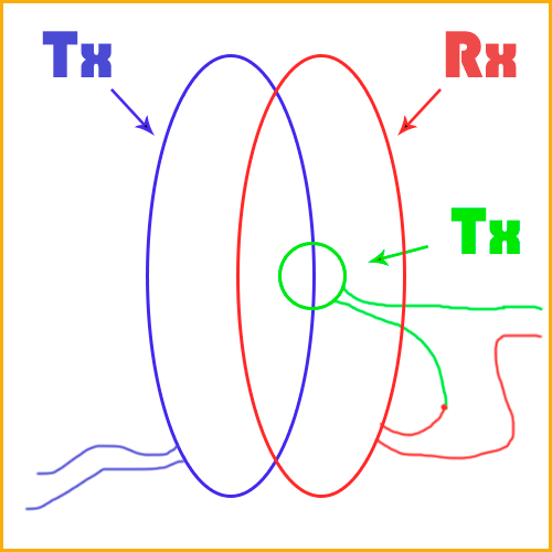
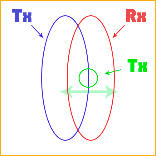
diameter Rx and Tx 16cm
Hocam bu yazımı nasıl indirebirim yardimci olurumusnuz
Great job my friend … Wishing for you all the best
Thank you!
Hola Sergei,
En play store no hay el app para usar el Smart hunter, como se ve aquí, hay otro pero no parece muy completo…
Hello, when do you expect to have discriminator complete and LM386 amp version?
Greeting
I would like to buy a metal detector.
How and where to order it and how much it costs.
Kisic Ljubomir
Belgrade Serbia